- WhatsApp: +86 15517539723
- [email protected]
- Mon - Sat 8:00 - 17:30, Sunday - CLOSED

Popular Products
-
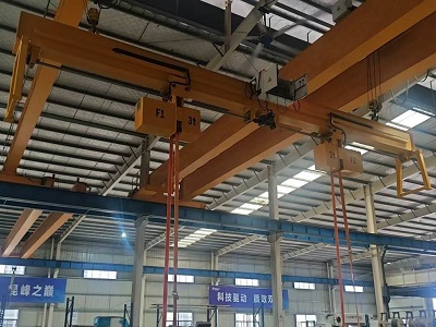
Suspended Load Rotator for Overhead Cranes
-

Ground-Mounted Belt Beam Rotator for Steel Structure Components
-

Custom Chain Type Beam Rotator | 360° Heavy Workpiece Turning
-
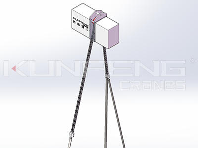
Safe Lifting Load-Levelling Device
-
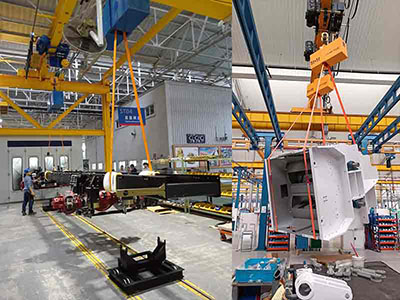
Load Rotating Beam for Container Spreader Assembly
-
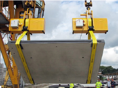
180 Degree Load Rotation Equipment
-
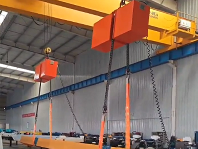
Load Turning Devices & Roll-Over Units
-
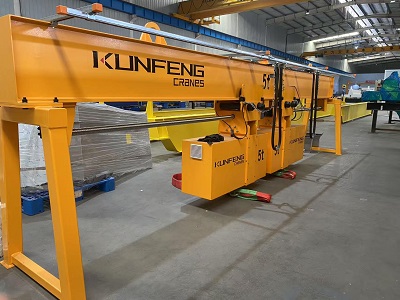
Turnover Spreader Beams for Rotating Heavy Loads
-
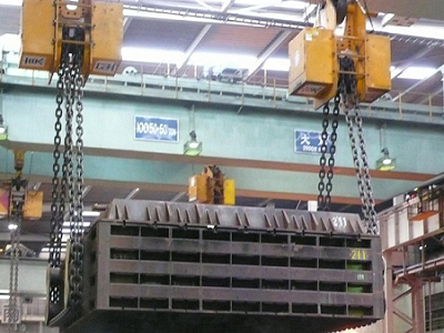
Chain Load Turning Beam
-
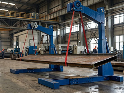
Ground Mounted Beam Rotator
Contact Info
Address:
No.19 Industry Park, Dongtai, Jiangsu, China
Email:
[email protected]
WhatsApp:
+86 15517539723
WeChat:
15517539723
Suspended Load Rotator for Overhead Cranes
Category: Load Turning Device
Looking for a suspended load rotator for overhead cranes? Learn how to evaluate crane lifting height, turning envelopes, and workpiece dimensions. Request a free technical assessment!
Email:[email protected]
Contact Us For Quotation
Product Details
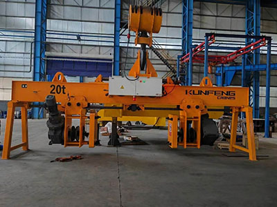
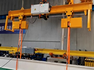
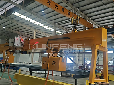
The load rotator is suspended securely from the overhead crane via its main hook, allowing operators to rotate bulky workpieces smoothly from 0° to 360° during assembly and welding for faster turnaround and effortless multi-angle access.
Working Principle of Crane-Suspended Load Rotator
Installed between the overhead crane hook and the load, the rotator integrates seamlessly with the crane via heavy-duty connecting rigging. During operation, the crane handles vertical lifting and horizontal travel, while the rotator's electric motor drives its internal gear mechanism to turn the suspended workpiece in the desired direction.
Via the control system, operators can easily adjust both rotational speed and direction to achieve continuous 360° rotation or precise angular positioning. Throughout the welding, inspection, and assembly of large components, the unit maintains rock-solid load stability—minimizing sway and impact forces while dramatically improving overall operational accuracy.


Core Logic of Overhead Crane and Load Rotator Coordination
During operation, the load rotator transitions workpieces from a horizontal to a vertical position, causing a dramatic shift in the workpiece's center of gravity. The overhead crane is not only responsible for smoothly loading and unloading the workpieces onto and off the load rotator; in certain load rotator designs, the crane may also need to work in tandem with the load rotator for synchronized turning or safely lifting the rotated workpiece away.
Therefore, the technical parameters of your overhead crane directly effects whether the load rotator can be successfully implemented and operated efficiently on your shop floor.
Must-Read for Customers: Two Core Focus Areas
When evaluating whether your workshop crane meets the operational requirements of a tilter, the following two points must serve as your primary assessment criteria:
1. Focus Area One: Factory Crane Lifting Height
Lifting height refers to the vertical distance from the highest point of the crane hook to the workshop floor. This is a rigid metric that users most frequently overlook, yet it is the most common source of operational bottlenecks.
Why is it important? When a workpiece transitions from a "horizontal" to a "vertical" orientation on the load rotator, its highest point extends significantly upward.
Calculation Logic: To ensure sufficient clearance, the crane's effective lifting height must exceed the combined total of:
Load rotator table height
Height of the upright workpiece
Rigging headroom (wire ropes, slings, or spreader beams)
Safety margin (typically 300–500 mm)
Common Pitfall: Older workshops often have lower crane lifting heights. Consequently, as soon as the workpiece is stood upright, the crane hook hits its upper limit (colliding with the main girder or hoist body), making it impossible to complete the lift or unhook the load.
2. Focus Area Two: Workpiece Dimensions & Spatial Turning Envelope
The external dimensions (length, width, and height) of the workpiece are closely tied to the structural design of the load rotator and directly dictate the crane's spatial clearance during operation.
Dimensional Alignment & Center of Gravity: The crane's lifting points must align precisely with the workpiece's center of gravity. If the workpiece is oversized or off-center, it can sway or tilt during hoisting, preventing smooth placement into the sling turning zone or causing uneven load distribution across the slings.
Spatial Interference During Tilting: During the tilting process, the workpiece sweeps through a "turning envelope." The crane's wire ropes, slings, and bridge girder structure must remain completely clear of this envelope to prevent collisions with the workpiece while tilting or hoisting.
Key Dimension Verification: When selecting equipment, you must provide not only the maximum weight of the workpiece, but also its maximum external dimensions (L × W × H) and dimensional state changes before and after tilting.
3. Additional Crane Factors for Supplementary Evaluation
Beyond lifting height and workpiece dimensions, the following crane factors also impact the smooth operation of a load rotator:
Rated Lifting Capacity (Tonnage): Ensure your crane's Safe Working Load (SWL) exceeds the total combined weight of the workpiece, the suspended load rotator, and all auxiliary lifting rigging, while maintaining an appropriate safety margin.
Operating Speed & Micro-Speed Performance: When tilting and hoisting precision workpieces, the crane should ideally feature variable frequency drive (VFD) speed control or micro-speed (inching) capabilities to prevent sudden starts or stops from causing the workpiece to impact the load rotator.
Workshop Span & Hook Limit Positions: Evaluate the coverage area of the crane bridge and trolley within the plant to ensure the load rotator is installed well outside the crane's hook blind spots.
Get Your Custom Load Rotator Assessment Today!
Planning to add a load rotator to your production line? Send us the following details for a quick technical evaluation by our engineers:
Crane Specs: Lifting height, rated capacity (SWL), and workshop span
Workpiece Details: Max dimensions (L × W × H), max weight, and required rotation angle (90°/180°)
Contact Us Now to find the safest and most efficient load rotator for your workshop!
Send Us Your Requirement
Customer Cases
Recommend News
- 2025-01-21 Features of Truck Chassis Load Rotator
- 2026-04-03 A Comprehensive Guide on How to Buy Rotator Turning Device
- 2025-06-19 Rotating Lifting Beam for Flipping Loads
- 2025-02-07 Application Scenarios of The Turning Device on Crane Hook
- 2026-07-29 Design Features of Electric Load Turning Device
- 2026-08-26 How Double-Chain Synchronous Drives Optimize Load Turning
- 2026-09-05 Understanding Load Turning Devices: Applications, Advantages, and Selection
- 2025-12-15 Belt Sling Rotator Turning Device for Rotating Steel Slab
- 2025-05-26 Turning Device Installed on Crane Lifting Beam
- 2025-11-19 Can The Load Turning Units be Customized for Requirements